Original CONTENTS OF THE BOOK in
BLUE with
EXPLANATIONS
and FIGURES Inserted.
Section
1 -
TECHNOLOGY OVERVIEW- Explanation-
This section provides an overview of fuel cell technology. First it
discusses the basic workings
of fuel cells and basic fuel cell system components. Then, an
overview of the main fuel cell
types, their characteristics, and their development status is
provided. Finally, this chapter reviews
potential fuel cell applications.
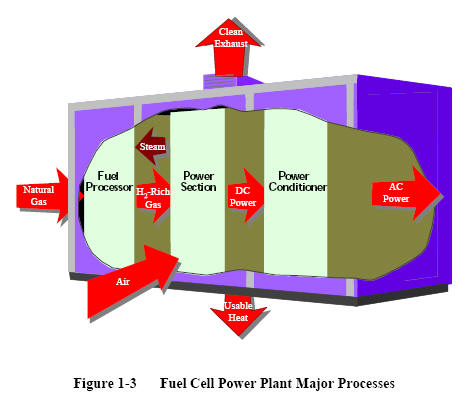 |
Figure 1-3 shows a simple rendition of a fuel cell power
plant. Beginning with fuel processing, a
conventional fuel (natural gas, other gaseous hydrocarbons, methanol,
naphtha, or coal) is cleaned, then converted into a
gas containing hydrogen. Energy conversion occurs when dc
electricity is generated by means of individual fuel cells
combined in stacks or bundles. A varying number of cells or
stacks can be matched to a particular power application.
Finally, power
conditioning converts the electric power from dc into
regulated dc or ac for consumer use. Section 8.1
describes
the processes of a fuel cell power plant system.
|
 |
1.6 Characteristics
The interest in terrestrial applications of fuel cells is
driven primarily by their potential for high
efficiency and very low environmental impact (virtually no
acid gas or solid emissions). Efficiencies
of present fuel cell plants are in the range of 30 to 55
percent based on the lower heating value (LHV) of the
fuel. Hybrid fuel cell/reheat gas turbine cycles that offer
efficiencies greater than
70 percent LHV, using demonstrated cell performance, have
been proposed.
Figure 1-4 illustrates demonstrated low emissions of
installed PAFC units compared to the Los Angeles Basin
(South Coast Air Quality Management District) requirements,
the strictest requirements in the U. S. Measured
emissions from the PAFC unit are < 1 ppm of NOX,
4 ppm of CO, and <1 ppm of reactive organic gases
(non-methane) (5). In addition, fuel cells operate at
a constant temperature,
and the heat from the electrochemical reaction is available
for cogeneration applications. Table summarizes the
impact of the major constituents within fuel gases on the
various fuel cells. The reader is referred to Sections 3
through 7 for detail on trace contaminants.
|
|
|
1.1 |
INTRODUCTION.. |
1-1
|
|
|
1.2 |
UNIT
CELLS.. |
1-2 |
|
|
|
1.2.1
Basic Structure.. |
1-2 |
|
|
|
1.2.2
Critical Functions of Cell Components..
|
1-3 |
|
|
1.3 |
FUEL CELL
STACKING.. |
1-4 |
|
|
|
1.3.1
Planar-Bipolar Stacking.. |
1-4 |
|
|
|
1.3.2
Stacks with Tubular Cells.. |
1-5 |
|
|
1.4 |
FUEL CELL
SYSTEMS.. |
1-5 |
|
|
1.5 |
FUEL CELL
TYPES.. |
1-7 |
|
|
|
1.5.1
Polymer Electrolyte Fuel Cell (PEFC)..
|
1-9 |
|
|
|
1.5.2
Alkaline Fuel Cell (AFC).. |
1-10 |
|
|
|
1.5.3
Phosphoric Acid Fuel Cell (PAFC).. |
1-10 |
|
|
|
1.5.4
Molten Carbonate Fuel Cell (MCFC).. |
1-11 |
|
|
|
1.5.5
Solid Oxide Fuel Cell (SOFC).. |
1-12 |
|
|
1.6 |
CHARACTERISTICS.. |
1-12 |
|
|
1.7 |
ADVANTAGES/DISADVANTAGES.. |
1-14 |
|
|
1.8 |
APPLICATIONS, DEMONSTRATIONS, AND STATUS..
|
1-15 |
|
|
|
1.8.1
Stationary Electric Power.. |
1-15 |
|
|
|
1.8.2
Distributed Generation.. |
1-20 |
|
|
|
1.8.3
Vehicle Motive Power.. |
1-22 |
|
|
|
1.8.4
Space and Other Closed Environment Power..
|
1-23 |
|
|
|
1.8.5
Auxiliary Power Systems.. |
1-23 |
|
|
|
1.8.6
Derivative Applications.. |
1-32 |
|
|
1.9 |
REFERENCES.. |
1-32 |
Section
2 -
FUEL CELL PERFORMANCE
- Explanation-
The purpose of this section is
to describe the chemical and thermodynamic relations governing
fuel cells and how operating conditions affect their
performance. Understanding the impacts of
variables such as temperature,
pressure, and gas constituents on performance allows fuel cell
developers to optimize their design of the modular units and it
allows process engineers to maximize the performance of
systems applications.
 |
A
wide variety of fuel
cell models has been developed. While fundamentally the
constitutive equations such as those described in this
chapter underlie all models, their level of detail,
level of aggregation, and numerical implementation method
vary widely. A useful categorization of fuel cell models is
made by level of aggregation, as shown in Figure 2-9.
As implied in the figure, the outputs
of the more detailed fundamental models can be used in
lower-order models. This flow of information is, in fact, a
critical application for high fidelity models. Recently,
much work has been done in the development of algorithms to
integrate or embed high-fidelity models into system analysis
simulation tools.
|
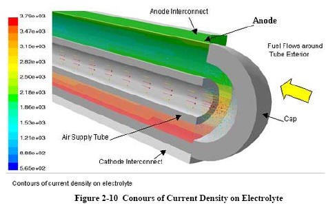 |
NETL's 3-D Analysis
The National Energy
Technology Laboratory (NETL) developed a 3-dimensional
computational fluid dynamics (CFD) model to allow stack
developers to reduce time-consuming build-and-test
efforts. As opposed to systems models, 3-dimensional CFD
models can address critical issues
such as temperature profiles and fuel utilization; important
considerations in fuel cell development.
CFD
analysis computes local fluid velocity, pressure, and
temperature throughout the region of interest for problems
with complex geometries and boundary conditions. By coupling
the CFDpredicted fluid
flow behavior with the electrochemistry and accompanying
thermodynamics, detailed predictions are possible.
Improved knowledge of temperature and flow conditions at all
points in the fuel cell lead to improved design and
performance of the unit. |
|
2.1 |
THE ROLE OF GIBBS FREE ENERGY AND
NERNST
POTENTIAL.. |
2-1 |
|
2.2 |
IDEAL PERFORMANCE.. |
2-4 |
|
2.3 |
CELL ENERGY BALANCE.. |
2-7 |
|
2.4 |
CELL EFFICIENCY.. |
2-7 |
|
2.5 |
ACTUAL PERFORMANCE.. |
2-10 |
|
2.6 |
FUEL CELL PERFORMANCE VARIABLES.. |
2-18 |
|
2.7 |
MATHEMATICAL MODELS.. |
2-24 |
|
|
2.7.1 Value-in-Use Models.. |
2-26 |
|
|
2.7.2 Application Models.. |
2-27 |
|
|
2.7.3 Thermodynamic System Models..
|
2-27 |
|
|
2.7.4 3-D Cell / Stack Models.. |
2-29 |
|
|
2.7.5 1-D Cell Models.. |
2-31 |
|
|
2.7.6 Electrode Models.. |
2-32 |
|
2.8 |
REFERENCES.. |
2-33 |
Section
3 -
POLYMER ELECTROLYTE FUEL CELLS
- Explanation-
This section includes an in depth discussion of Polymer electrolyte
membrane fuel cells (PEFC), which are able to efficiently generate
high power densities, thereby
making the technology potentially attractive for certain mobile and
portable applications.
 |
3.1 Cell Components
Typical cell components within a PEFC
stack include:
·
the ion exchange membrane
·
an electrically conductive porous backing
layer
·
an electro-catalyst (the electrodes) at the interface
between the backing
layer and the membrane
·
cell interconnects and flowplates that deliver the fuel and
oxidant to
reactive sites via flow channels and
electrically connect the cells
(Figure 3-1).
PEFC stacks are almost
universally of the planar bipolar type. Typically, the
electrodes are cast as thin films that are either
transferred to the membrane or applied directly to the
membrane. Alternatively, the catalyst-electrode layer may be
deposited onto the backing layer, then bonded to the
membrane.
|
|
3.1 |
CELL
COMPONENTS..
|
3-1 |
|
|
3.1.1 State-of-the-Art Components..
|
3-2 |
|
|
3.1.2 Component Development.. |
3-11 |
|
3.2 |
PERFORMANCE.. |
3-14 |
|
3.3 |
PEFC
SYSTEMS.. |
3-16 |
|
|
3.3.1 Direct Hydrogen PEFC Systems..
|
3-16 |
|
|
3.3.2 Reformer-Based PEFC Systems .. |
3-17 |
|
|
3.3.3
Direct Methanol Fuel Cell Systems..
|
3-19 |
|
3.4 |
PEFC
APPLICATIONS.. |
3-21 |
|
|
3.4.1 Transportation Applications..
|
3-21 |
|
|
3.4.2 Stationary applications.. |
3-22 |
|
3.5 |
REFERENCES.. |
3-22 |
Section
4 -
ALKALINE FUEL CELL
- Explanation-
This section discusses the
Alkaline Fuel Cell (AFC), which was one of the first modern fuel
cells to be developed, beginning in 1960. The application at
that time was to provide on-board electric power for the Apollo
space vehicle. Desirable attributes of the AFC include excellent
performance compared to other candidate fuel cells due to its active
O2 electrode kinetics and
flexibility to use a wide range of electro-catalysts. The AFC
continues to be used: it now provides on-board power for the Space
Shuttle Orbiter with cells manufactured by UTC Fuel Cells.
 |
 |
|
Figures 4-1 and 4-2 depict the operating configuration of
the H2/O2 alkaline fuel cell (8) and a H2/air
cell (9). In both, the half-cell reactions are: |
H2 + 2OH→
2H2O
+ 2e- (Anode)
½O2
+ H2O
+ 2e- →
2OH¯ (Cathode) |
| |
|
|
|
|
4.1 |
CELL
COMPONENTS..
|
4-5 |
|
|
|
4.1.1
State-of-the-Art Components.. |
4-5 |
|
|
|
4.1.2 Development
Components.. |
4-6 |
|
|
4.2 |
PERFORMANCE...
|
4-7 |
|
|
|
4.2.1 Effect of
Pressure.. |
4-8 |
|
|
|
4.2.2 Effect of
Temperature.. |
4-9 |
|
|
|
4.2.3 Effect of
Impurities.. |
4-11 |
|
|
|
4.2.4 Effects of
Current Density.. |
4-12 |
|
|
|
4.2.5 Effects of Cell
Life.. |
4-14 |
|
|
4.3 |
SUMMARY
OF EQUATIONS
FOR AFC..
|
4-14 |
|
|
4.4 |
REFERENCES..
|
4-16 |
Section
5 -
PHOSPHORIC ACID FUEL CELL
- Explanation-
This section discusses the
Phosphoric Acid Fuel Cell (PAFC), which was the first fuel cell
technology to be commercialized. The
number of units built exceeds any other fuel cell technology, with
over 85 MW of demonstrators
that have been tested, are being tested, or are being fabricated
worldwide.
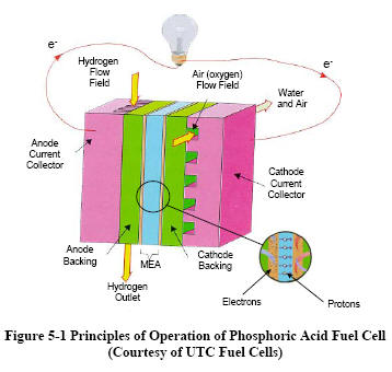 |
Figure 5-1 depicts the
operating configuration of the phosphoric acid cell. The
electrochemical
reactions occurring in PAFCs are H2→2H++2e-
at the anode, and
½ O2
+ 2H+
+ 2e−
→ H2O
at the cathode. The
overall cell reaction is ½
O
2
+
H2
—> H2O
The electrochemical reactions occur on highly dispersed
electro-catalyst particles supported on carbon black.
Platinum (Pt) or Pt alloys are used as the catalyst at both
electrodes.
|
| |
|
|
5. |
PHOSPHORIC ACID FUEL CELL |
5-1 |
|
|
5.1 |
CELL
COMPONENTS..
|
5-2 |
|
|
|
5.1.1
State-of-the-Art Components.. |
5-2 |
|
|
|
5.1.2
Development Components.. |
5-6 |
|
|
5.2 |
PERFORMANCE..
|
5-11 |
|
|
|
5.2.1
Effect of Pressure.. |
5-12 |
|
|
|
5.2.2
Effect of Temperature.. |
5-13 |
|
|
|
5.2.3
Effect of Reactant Gas Composition and Utilization..
|
5-14 |
|
|
|
5.2.4
Effect of Impurities.. |
5-16 |
|
|
|
5.2.5
Effects of Current Density.. |
5-19 |
|
|
|
5.2.6
Effects of Cell Life.. |
5-20 |
|
|
5.3 |
SUMMARY
OF EQUATIONS
FOR PAFC..
|
5-21 |
|
|
5.4 |
REFERENCES..
|
5-22 |
Section
6 -
MOLTEN CARBONATE FUEL CELL
- Explanation-
This section discusses
Molten Carbonate Fuel Cells, which are being developed for natural
gas and coal-based power
plants for industrial, electrical utility, and military
applications.
 |
There are two alternate
approaches to internal reforming molten carbonate cells:
indirect internal reforming (IIR) and direct internal
reforming (DIR). In the first approach, the reformer section
is separate, but adjacent to the fuel cell anode. This cell
takes advantage of the close-coupled thermal benefit where
the exothermic heat of the cell reaction can be used for the
endothermic reforming reaction. Another advantage is that
the reformer and the cell environments do not have a direct
physical effect on each other. A disadvantage is that the
conversion of methane to hydrogen is not promoted as well as
in the direct approach. In the DIR cell, hydrogen
consumption reduces its
partial pressure, thus
driving the methane reforming reaction, Equation (6-34), to
the right. Figure 6-12 depicts one developer's
approach where IIR and DIR have been combined.
|
| |
|
|
|
|
6.1 |
CELL
COMPONENTS..
|
6-4 |
|
|
|
6.1.1 State-of-the-Art Componments..
|
6-4 |
|
|
|
6.1.2 Development Components.. |
6-9 |
|
|
6.2 |
PERFORMANCE..
|
6-13 |
|
|
|
6.2.1 Effect of Pressure.. |
6-15 |
|
|
|
6.2.2 Effect of Temperature.. |
6-19 |
|
|
|
6.2.3 Effect of Reactant Gas Composition and
Utilization.. |
6-21 |
|
|
|
6.2.4 Effect of Impurities.. |
6-25 |
|
|
|
6.2.5 Effects of Current Density..
|
6-30 |
|
|
|
6.2.6 Effects of Cell Life.. |
6-30 |
|
|
|
6.2.7 Internal Reforming.. |
6-30 |
|
|
6.3 |
SUMMARY
OF EQUATIONS
FOR MCFC..
|
6-34 |
|
|
6.4 |
REFERENCES.. |
6-38 |
Section
7 -
SOLID OXIDE FUEL CELLS
- Explanation-
This section discusses
Solid Oxide Fuel Cells (SOFCs), which have an electrolyte that is a
solid, non-porous metal oxide,
usually Y2O3-stablilized
ZrO2.
The cell operates at 600-1000
oC
where ionic conduction by oxygen ions takes
place.
 |
Sensitivity to
sulfur and other contaminants. Strong reversible
poisoning of the anode occurs at feed concentrations
ranging from about 1 ppm H2S
when operating at 1000 °C down to less than 50 ppb when
operating at 750 °C (Figure 7-2a (16, 17)). These
concentrations require desulfurization of the anode
feed, even if it is produced from low-sulfur fuels such
as natural gas or ultra-low sulfur diesel or gasoline
(Figure 7-2b). No data is available publicly on the
impact of other species (water or hydrocarbons) or
different sulfur species on sulfur tolerance, or on the
effect after long periods of time (e.g. 40,000 hours or
more). Another strong anode poison reported is HCl.
Poisoning by these species is reversible after exposure
at low concentrations, but irreversible after exposure
at concentrations above about 200 ppm.
|
 |
Lower operating temperatures would allow the use of ferritic
steels, that could reduce the materials cost, and ferritic
steels are typically easier to process with low-cost
processing techniques. The corrosion resistance of steel
depends on the formation of stable oxide layers on
the surface (Figure 7-5). After extensive testing of
commercial compositions, it was concluded
that none possessed the
corrosion resistance required, especially to withstand the
thermal cycling requirements while still providing adequate
contact resistance. Efforts were undertaken to develop more
suitable compositions, which led to the development of
several special alloys. Many developers now use the Krupp
formulation Crofer22 APU. |
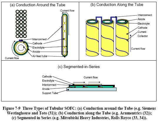 |
Tubular
SOFC
Although the Siemens Westinghouse design of tubular SOFC is
by far the best-known and most developed, two other types of
tubular SOFCs, shown in Figure 7-9 illustrate ways in which
the cells are interconnected. Numerous other designs have
been proposed, but are no longer pursued. |
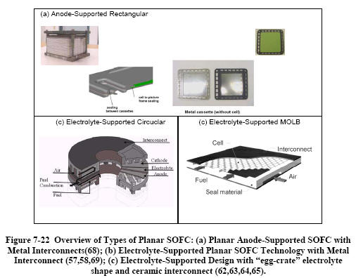 |
Figure 7-22 shows a sample of
recently-pursued planar SOFC approaches. The anode-supported
technology with metal interconnects will be described in
some detail below. Mitsubishi tested a
15 kW system with its
all-ceramic MOLB design for almost 10,000 hours with
degradation rates below 0.5 percent per 1,000 hrs,
but without thermal cycles, and with power densities ranging
from 190 to 220 mW/cm2 (under practical operating
conditions). Because the interconnect is flat
and relatively thin (the
flow-passage is embedded in the MEA), less of the expensive
LaCrO3
is required than if the flow-passages were in the
interconnect. Nevertheless, cost reduction is still
one of the main priorities for this stack technology.
Thermal cycling is also thought to be a
challenge with the system, which is targeted to small-scale distributed
stationary power generation applications. |
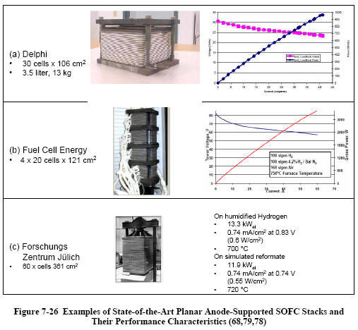 |
Stack Performance
A number of planar cell
stack designs have been developed based on planar
anode-supported SOFC with metal interconnects. Typically,
cells for full-scale stacks are about 10 to 20 cm mostly
square or rectangular (though some are round). Stacks with
between 30 and 80 cells are the state-of-the-art.
Figure 7-26 shows examples of state-of-the art planar
anode-supported SOFC
stacks and selected performance data (68,78, 79). The stacks
shown are the result of three to seven generations of
full-scale stack designs by each of the developers. The
capacities of these stacks (2 to 12 kW operated on reformate
and at 0.7 V cell voltage) is sufficient for certain
small-scale stationary and mobile (APU) applications.
|
| |
7.1 CELL COMPONENTS..
7.1.1 Electrolyte Materials..
7.1.2 Anode Materials..
7.1.3 Cathode Materials ..
7.1.4 Interconnect Materials..
7.1.5 Seal Materials..
7.2 CELL AND STACK DESIGNS..
7.2.1 Tubular SOFC..
7.2.1.1 Performance..
7.2.2 Planar SOFC..
7.2.2.1 Single Cell Performance..
7.2.2.2 Stack Performance..
7.2.3 Stack Scale-Up..
7.3 SYSTEM CONSIDERATIONS..
7.4 REFERENCES.. |
7-2
7-2
7-3
7-5
7-6
7-9
7-13
7-13
7-20
7-31
7-35
7-39
7-41
7-45
7-45 |
Section
8 -
FUEL CELL SYSTEMS
- Explanation-
This section discusses
fuel cell power systems, which consist of
a fuel processor, fuel cell power section, power conditioner, and
potentially a cogeneration or
bottoming cycle to utilize the rejected heat.
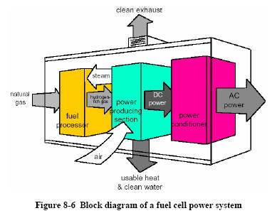 |
Figure 8-6 shows a block
diagram of a representative fuel cell power plant. Natural
gas flows to a fuel processor, where the methane is reformed
to hydrogen-rich gas. The hydrogen gas reacts in the power
producing section, which consists of a fuel cell. The DC
power generated by the
fuel cell must be converted to AC power; one of the power
conditioning approaches identified above would be
selected, based on the specific application.
|
 |
8.2.9 System Issues: Power Conversion Cost and Size
400V DC is required to produce 120V/240V AC. If a fuel cell
can produce 400V DC, then only an inverter stage is
required, resulting in lowest cost for power conditioning.
Present day commercially available fuel cells produce
low voltage (12V to 100V). Therefore, either a line
frequency transformer to
increase the AC voltage or a DC-DC converter to boost the DC
voltage is required, adding to cost, weight, and volume.
Figure 8-24 shows a representative cost per kW of the power
conditioning unit, as the voltage and current values are
varied for a certain power level. It is clear from this
figure that extremes of voltage at low power and high
current at high power levels does not result in an
optimum design. In general, higher voltage levels are
required at higher power
outputs to minimize the cost of power conditioning hardware.
The other issue is power density and size of power
conditioning unit. Using higher switching frequency for
power conversion should result in smaller size. However, the
switching losses are higher and a design compromise becomes
necessary. Employing power semiconductor devices with lower
losses combined with active cooling methods should yield an
optimum size. Power integrated circuits can also be
considered for further size reduction and become viable, if
the fuel cell systems are produced in high volume. |
|
8.1 SYSTEM
PROCESSES..
8.1.1 Fuel Processing..
8.2 POWER
CONDITIONING..
8.2.1 Introduction to Fuel Cell Power Conditioning
Systems..
8.2.2 Fuel Cell Power Conversion for Supplying a
Dedicated Load [2,3,4]..
8.2.3 Fuel Cell Power Conversion for Supplying Backup
Power to a Load
Connected to a Local Utility..
8.2.4 Fuel Cell Power Conversion for Supplying a Load
Operating in Parallel
With the Local Utility (Utility Interactive)..
8.2.5 Fuel Cell Power Conversion for Connecting
Directly to the Local Utility..
8.2.6 Power Conditioners for Automotive Fuel Cells..
8.2.7 Power Conversion Architecture for a Fuel Cell
Turbine Hybrid Interfaced
With a Local Utility..
8.2.8 Fuel Cell Ripple Current..
8.2.9 System Issues: Power Conversion Cost and Size..
8.2.10 REFERENCES
(Sections 8.1 and
8.2)..
8.3 SYSTEM
OPTIMIZATION..
8.3.1 Pressure..
8.3.2 Temperature..
8.3.3 Utilization..
8.3.4 Heat Recovery..
8.3.5 Miscellaneous..
8.3.6 Concluding Remarks on System Optimization..
8.4 FUEL
CELL
SYSTEM
DESIGNS..
8.4.1 Natural Gas Fueled PEFC System..
8.4.2 Natural Gas Fueled PAFC System..
8.4.3 Natural Gas Fueled Internally Reformed MCFC
System..
8.4.4 Natural Gas Fueled Pressurized SOFC System..
8.4.5 Natural Gas Fueled Multi-Stage Solid State
Power Plant System..
8.4.6 Coal Fueled SOFC System..
8.4.7 Power Generation by Combined Fuel Cell and Gas
Turbine System..
8.4.8 Heat and Fuel Recovery Cycles.. |
8-2
8-2
8-27
8-28
8-29
8-34
8-37
8-37
8-39
8-41
8-43
8-44
8-45
8-46
8-46
8-48
8-49
8-50
8-51
8-51
8-52
8-52
8-53
8-56
8-58
8-62
8-66
8-70
8-70
|
|
|
8.5.2 MCFC Network..
|
8-86
|
|
|
8.5.3 Recycle Scheme..
|
8-86
|
|
|
8.5.4 Reactant Conditioning Between Stacks in
Series..
|
8-86
|
|
|
8.5.5 Higher Total Reactant Utilization..
|
8-87
|
|
|
8.5.6 Disadvantages of MCFC Networks..
|
8-88
|
|
|
8.5.7 Comparison of Performance..
|
8-88
|
|
|
8.5.8 Conclusions..
|
8-89
|
|
8.6 |
HYBRIDS..
|
8-89
|
|
|
8.6.1 Technology..
|
8-89
|
|
|
8.6.2 Projects..
|
8-92
|
|
|
8.6.3 World’s First Hybrid Project..
|
8-93
|
|
|
8.6.4 Hybrid Electric Vehicles (HEV)..
|
8-93
|
|
8.7 |
FUEL
CELL
AUXILIARY
POWER
SYSTEMS..
|
8-96
|
|
|
8.7.1 System Performance Requirements..
|
8-97
|
|
|
8.7.2 Technology Status..
|
8-98
|
|
|
8.7.3 System Configuration and Technology Issues..
|
8-99
|
|
|
8.7.4 System Cost Considerations..
|
8-102
|
|
|
8.7.5 SOFC System Cost Structure..
|
8-103
|
|
|
8.7.6 Outlook and Conclusions..
|
8-104
|
|
8.8 |
REFERENCES.. |
8-104 |
Section
9 -
SAMPLE CALCULATIONS
- Explanation-
This section presents sample
problems to aid the reader in understanding the calculations behind
a fuel cell power system.
The sample calculations are arranged topically with unit operations
in Section 9. 1, system
issues in Section 9.2, supporting calculations in Section 9.3, and
cost
calculations in Section 9.4. A list of
conversion factors common to fuel cell systems analysis is presented
in Section 9.5, and a sample automotive design calculation is
presented in Section 9.6.
|
9. |
SAMPLE CALCULATIONS.. |
9-1 |
|
|
9.1 |
UNIT
OPERATIONS.. |
9-1 |
|
|
|
9.1.1 Fuel Cell Calculations.. |
9-1 |
|
|
|
9.1.2 Fuel Processing Calculations.. |
9-13 |
|
|
|
9.1.3 Power Conditioners.. |
9-16 |
|
|
|
9.1.4 Others.. |
9-16 |
|
|
9.2 |
SYSTEM ISSUES.. |
9-16 |
|
|
|
9.2.1 Efficiency Calculations.. |
9-17 |
|
|
|
9.2.2 Thermodynamic Considerations..
|
9-19 |
|
|
9.3 |
SUPPORTING CALCULATIONS.. |
9-22 |
|
|
9.4 |
COST
CALCULATIONS.. |
9-25 |
|
|
|
9.4.1 Cost of Electricity.. |
9-25 |
|
|
|
9.4.2 Capital Cost Development.. |
9-26 |
|
|
9.5 |
COMMON CONVERSION FACTORS.. |
9-27 |
|
|
9.6 |
AUTOMOTIVE DESIGN CALCULATIONS.. |
9-28 |
|
|
9.7 |
REFERENCES.. |
9-29 |
Section
10 -
APPENDIX
| |
|
|
|
|
10.1 |
EQUILIBRIUM
CONSTANTS.. |
10-1 |
|
|
10.2 |
CONTAMINANTS
FROM COAL
GASIFICATION.. |
10-2 |
|
|
10.3 |
SELECTED
MAJOR
FUEL
CELL
REFERENCES,
1993
TO
PRESENT.. |
10-4 |
|
|
10.4 |
LIST
OF SYMBOLS.. |
10-10 |
|
|
10.5
10.6
10.7
10.8
10.9
10.10
|
FUEL
CELL
RELATED
CODES
AND STANDARDS..
10.5.5 Codes and
Standards for the Installation of Fuel Cells..
10.5.6 Codes and Standards for Fuel Cell Vehicles..
10.5.7 Application Permits..
10.5.8 References..
FUEL
CELL
FIELD
SITE
DATA...
10.6.1 Worldwide
Sites..
10.6.2 DoD Field Sites..
10. 6.3 IFC Field Units..
10.6.4 FuelCell Energy..
10.6.5 Siemens Westinghouse..
HYDROGEN..
10.7.1
Introduction..
10.7.2 Hydrogen Production..
10.7.3 DOE’s Hydrogen Research..
10.7.4 Hydrogen Storage..
10.7.5 Barriers..
HE
OFFICE
OF ENERGY
EFFICIENCY
AND RENEWABLE
ENERGY
WORK
IN FUEL
CELLS..
RARE
EARTH
MINERALS..
10.9.1
Introduction..
10.9.2 Outlook..
REFERENCES.. |
10-14
10-19
10-19
10-19
10-21
10-21
10-21
10-24
10-24
10-24
10-24
10-31
10-31
10-32
10-34
10-35
10-36
10-36
10-38
10-38
10-40
10-41 |
|


 BOTH
H2 DVDS
BOTH
H2 DVDS

 BOTH
Hydrogen Books
BOTH
Hydrogen Books BOTH
FUEL CELL BOOKS
BOTH
FUEL CELL BOOKS BOTH
FUEL CELL BOOKS &
BOTH
FUEL CELL BOOKS &


 Industrial
Hydrogen Book
Industrial
Hydrogen Book